Selecting Wear Blocks for Heavy Equipment: Hardness, Toughness, and Welding Installation Best Practices
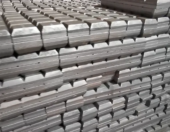
An engineering guide on selecting and installing wear blocks. Analyze the hardness-toughness trade-off and learn the welding procedures to prevent cracking.
Heavy machinery operates in highly demanding environments where wear liners are subjected to a combination of two destructive forces: abrasion and impact.
Selecting the right wear material is a balancing act. If the wear liner is too hard, it will be brittle and shatter under impact. If it is too soft, it will wear away rapidly under abrasion, leading to frequent maintenance shutdowns.
This guide provides a technical framework for evaluating the Hardness vs. Toughness trade-off, maps different wear block types to specific equipment zones, and details the welding installation procedures required to prevent cracking.
1. The Hardness-Toughness Trade-off in Wear Materials
In materials science, hardness (resistance to scratching/indentation) and toughness (resistance to fracture under impact) are generally inversely proportional.
Manganese Steel
200 HBAbsorbs extreme impact; work-hardens under load.
AR400 / AR500
400 - 500 HBBalanced wear plate for structural panels.
Bi-Metallic
700 HB / 63 HRCSevere sliding abrasion; weldable backing.
Tungsten Carbide
1500 HVExtreme abrasion resistance; zero impact tolerance.
To specify the correct wear block, engineers must evaluate the operating environment:
- High Impact / Low Abrasion: For example, primary crusher jaws or hopper walls receiving large boulders. Here, work-hardening manganese steel is preferred because it deforms and hardens under impact.
- Extreme Abrasion / Low-to-Medium Impact: For example, sand chutes, dredge pump liners, or excavator bucket shrouds. In these zones, bi-metallic wear blocks (700 HB) or tungsten carbide wear blocks are ideal because they resist micro-scratching.
2. Equipment Mapping: Where to Position Wear Blocks
To maximize wear life while controlling costs, plants utilize a “zoned” approach, placing different wear shapes in specific high-wear areas.
Excavator Bucket Wear Protection Zones
Zone 1: The Lip & Shrouds
High impact and high abrasion during penetration.
Specification: Bi-Metallic Chocky Bars & Heel Shrouds
Zone 2: Inside the Bucket (Deadbends)
Material slides along the floor, causing sliding abrasion.
Specification: Wear Buttons (creates rock-on-rock deadbeds)
Zone 3: Outer Cheek Plates
High friction against the trench walls during digging.
Specification: Wear Plates & Chocky Bars in Chevron Patterns
3. Welding Installation Guide for Bi-Metallic Wear Blocks
Since bi-metallic wear blocks consist of an ultra-hard white iron layer vacuum-brazed to a mild steel backing plate, incorrect welding procedures will cause thermal shock, resulting in cracks that propagate through the wear layer.
Follow this step-by-step engineering procedure to ensure a secure, crack-free installation:
Step 1: Surface Preparation
- Clean the target surface (bucket or chute steel) to remove rust, paint, grease, and moisture.
- Grind the area flat. Any air gaps beneath the wear block’s mild steel backing plate will cause bending stresses during operation, leading to bond failure.
Step 2: Preheating Requirements
- While the mild steel backing plate does not require preheating, the heavy equipment structure (often high-strength low-alloy steel like Q345 or Hardox) does.
- Preheat the parent metal to 100°C to 150°C (212°F to 300°F) around the weld zone to prevent hydrogen-induced cracking in the heat-affected zone (HAZ).
-
WARNING: Never apply direct heat to the white iron wear layer. Only heat the parent steel structure.
Step 3: Welder Settings & Consumables
- Welding Process: Shielded Metal Arc Welding (SMAW / Stick) or Gas Metal Arc Welding (GMAW / MIG) is recommended.
- Consumables: Use low-hydrogen electrodes such as E7018 (or wire equivalents like E71T-1).
- Current: Keep the heat input as low as possible. Use a welding current of 120A to 140A for a 3.2mm electrode.
Step 4: Welding Sequence
- Tack Welding: Tack weld the wear block at the center of both sides.
- Stitch Welding: Weld from the center outward to the corners. Avoid continuous high-heat passes; instead, use intermittent stitch welds to minimize thermal accumulation.
- Weld Size: A fillet weld size of 6mm to 8mm is typically sufficient. Do not overweld, as excessive weld volume increases shrinkage stresses.
Welding Sequence (Stitch from Center Outward):
       [ Corner 3 ] <======= [ Tack Center ] =======> [ Corner 1 ]
       [ Corner 4 ] <======= [ Tack Center ] =======> [ Corner 2 ]
Step 5: Post-Weld Cooling
- Allow the welded assembly to cool slowly in still air.
- Never quench the welds with water or force-cool them with compressed air. Rapid cooling will induce thermal shock, instantly cracking the 700 HB white iron wear layer.
Conclusion: Optimize Your Wear Life with VOTNE
Proper selection and correct installation are the keys to maximizing the return on your wear liner investment. At VOTNE, our wear blocks are engineered with a ductile Q235 steel backing that makes welding straightforward and safe. By following our thermal management and welding guidelines, you can eliminate installation cracks and ensure your equipment stays in the field longer.
Contact our engineering team today for custom layout drawings, welding support, or to request a quote.
- Email: engineering@votne.com
- Technical Support: Fill out our Contact Form to consult with a B2B parts specialist.
Etiquetas
Recursos Relacionados
Concrete Mixer Liner Maintenance & Replacement Guide: Troubleshooting Wear Patterns, Bolt Torque Specs, and Downtime Reduction
Uneven liner wear and loose countersunk bolts are the leading causes of mixer drum gouging and unscheduled downtime in batching plants. This guide covers step-by-step maintenance protocols, clearance tuning, and failure prevention.
How to Select and Optimize Conveyor Rollers for Heavy-Duty Industrial Applications
Conveyor rollers are the unsung heroes of bulk material handling. Specifying the correct tube thickness, bearing clearance, and sealing system can reduce operational downtime by up to 40%.
Concrete Mixer Arm Maintenance & Troubleshooting Guide: Preventing Keyway Shearing, Arm Fracture, and Blade Alignment Failures
Loose hub clamp bolts and misaligned mixing arms are the leading causes of mixer shaft keyway shearing and severe liner gouging. Follow this field maintenance guide to calibrate arm pitch and eliminate emergency downtime.