Concrete Mixer Liner Maintenance & Replacement Guide: Troubleshooting Wear Patterns, Bolt Torque Specs, and Downtime Reduction
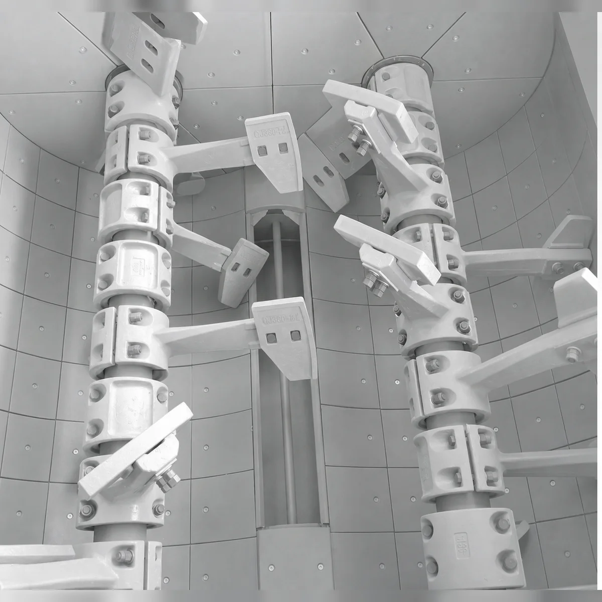
An authoritative field maintenance guide for concrete batching plant managers. Learn how to diagnose uneven mixer liner wear, prevent bolt hole cracking, select wall vs. drum vs. end liners, and extend wear life by 300%.
In high-volume commercial ready-mix concrete plants and precast manufacturing facilities, the concrete mixer is the single point of failure for the entire operation. When a mixer is forced offline due to worn-through liners, sheared countersunk bolts, or cracked wall plates, production halts completely. Deliveries are delayed, transit mixers sit idle, and concrete pumps on job sites stand waiting at immense financial expense.
While selecting high-grade materials like Cr20 or Cr26 high-chromium alloy liners is essential for long wear life, routine inspection, correct clearance tuning, and disciplined maintenance protocols are equally vital. In fact, field audits conducted by the RAXMEK Field Engineering Group reveal that over 45% of premature mixer liner failures stem from preventable installation errors, improper blade clearance, or neglected bolt tensioning.
This comprehensive technical guide delivers practical, field-tested troubleshooting procedures, failure analysis diagnostics, and step-by-step maintenance protocols to help plant managers, maintenance engineers, and equipment operators maximize mixer uptime and achieve peak wear performance.
1. Concrete Mixer Liner Taxonomy & Functional Breakdown
A modern twin-shaft or planetary concrete mixer utilizes specialized liner plates tailored to distinct hydraulic and abrasive zones inside the mixing trough:
1. Central Trough Liners
Positioned directly under mixing shafts. Experiences the highest sliding friction and severe aggregate impact at material intersection zones.
2. End Wall Liners
Mounted around main shaft seal assemblies. Subjected to fine-slurry scouring, micro-grit packing, and axial slurry pressure.
3. Side Wall Liners
Protect upper vertical drum enclosure walls against splash turbulence, aggregate rebound, and chemical slurry oxidation.
4. Discharge Gate Liners
Curved plates mounted on the discharge door assembly. Undergoes extreme fluid shear during rapid gate opening under full batch weight.
1.1 Central Trough Liners (Bottom Liners)
Central trough liners experience the most severe mechanical loading. In twin-shaft mixers, material is constantly thrown toward the center intersection zone where the two counter-rotating shafts overlap. Consequently, central liners experience wear rates up to 1.5 to 2.0 times higher than peripheral liners.
1.2 Side Wall & End Liners
End wall liners surround the main shaft entry points. Fine cement grout and sand micro-particles tend to migrate into the clearance space between the mixing arm hub and the end liner. If the shaft seal fails or slurry packs tightly into this gap, high-pressure grinding occurs, leading to localized ring scouring.
1.3 Discharge Gate Liners
Discharge door liners must maintain a tight mechanical clearance (0.5 to 1.5mm) against the fixed trough liners to prevent cement paste leakage. Wear on gate liners leads to grout loss, leaving behind unmixed aggregate pockets and causing concrete segregation.
2. Diagnostic Troubleshooting Guide: Common Liner Failure Modes
When inspecting mixer liners during scheduled weekly maintenance, operators often observe irregular wear patterns. The chart below provides a diagnostic tool to identify root causes and apply corrective actions:
| Observed Symptom | Visual Appearance | Root Cause Analysis | Corrective Maintenance Action |
|---|---|---|---|
| Localized Groove Scouring | Deep parallel grooves cut into central trough liners | Mixing blade-to-liner clearance set too tight, or hard stone wedged in gap | Readjust mixing blade clearance to 3.0 to 5.0mm. Inspect blades for chipping. |
| Liner Edge Crack / Spalling | Cracking radiating from countersunk bolt holes | Excessive bolt torque without elastomeric washer, or warped mixer shell | Replace missing rubber backing washers; re-torque bolts using a calibrated torque wrench. |
| Loose or Sheared Bolts | Oval bolt head missing or sunken below surface | Thermal expansion or vibration loosening; failure to re-torque after 500 m³ | Use Nyloc lock nuts; apply threadlocker; re-torque after 24 hrs. |
| Accelerated Center Wear | Central liners worn paper-thin while end liners remain thick | Non-uniform batch feeding; aggregate dropped exclusively into center of drum | Adjust weigh hopper chute distribution to spread coarse aggregate evenly across trough. |
| Slurry Bleeding at Joints | Dried cement grout buildup between adjacent liner edges | Worn-out backing gasket or degraded joint sealant between liner plates | Apply high-tack RTV silicone or polyurethane sealant during liner installation. |
3. The Crucial Role of Blade-to-Liner Clearance Adjustment
One of the most frequent mistakes in batching plant maintenance is neglecting the gap between the concrete mixer blades and the mixer liners.
Coarse aggregate (20mm granite) gets crushed directly against the liner, causing severe gouging, blade chipping, motor current spikes, and premature failure.
Liquid cement slurry forms a protective fluid boundary layer over the liner, ensuring smooth rotation, uniform mixing, and minimal direct stone-to-metal gouging.
Stagnant concrete crust builds up on the liner surface, reducing effective mixing drum volume, creating batch contamination, and causing uneven discharge.
3.1 Recommended Clearance Values by Aggregate Size
- Fine Aggregate Concrete (Max aggregate size 10mm or less): Set clearance to 2.5 to 3.5mm.
- Standard Commercial Ready-Mix (Max aggregate size 20mm): Set clearance to 3.5 to 5.0mm.
- Heavy Dam / Mass Concrete (Max aggregate size 40mm or larger): Set clearance to 5.0 to 7.0mm.
RAXMEK Pro Tip: Inspect blade-to-liner clearance every 10,000 m³ of production. As mixing blades wear down, adjust the mixing arm mounting slots outward to maintain the target clearance.
4. Aggregate Hardness & Abrasion Index Impact on Liner Lifespan
The mineralogy of your local aggregate directly dictates how long high-chromium mixer liners will last. The table below illustrates how different aggregate types impact expected liner service life:
| Aggregate Type | Mineral Composition | Mohs Hardness | Abrasiveness Index (LCPC) | Expected Liner Life (RAXMEK Cr20) | Expected Liner Life (RAXMEK Cr26) |
|---|---|---|---|---|---|
| Limestone / Dolomite | CaCO3 | 3.0 – 3.5 | Low (50 to 150 g/t) | 180,000 to 250,000 m³ | 300,000 to 400,000 m³ |
| River Gravel / Silica Sand | SiO2 (Quartz) | 6.5 – 7.0 | High (800 to 1500 g/t) | 100,000 to 140,000 m³ | 180,000 to 240,000 m³ |
| Crushed Granite | Quartz + Feldspar | 6.0 – 7.0 | Very High (1200 to 1800 g/t) | 80,000 to 120,000 m³ | 150,000 to 200,000 m³ |
| Crushed Basalt / Iron Slag | Pyroxene + Plagioclase | 6.5 – 7.5 | Extreme (over 2000 g/t) | 60,000 to 90,000 m³ | 120,000 to 160,000 m³ |
5. Step-by-Step Liner Replacement Protocol
When replacing a complete set of trough or wall liners, following a standardized engineering procedure ensures worker safety, zero slurry leakage, and maximum liner life.
6-Step Sequential Liner Replacement Workflow
Step 1: Lockout / Tagout (LOTO) & Safety Preparation
Disconnect and pad-lock the main circuit breaker for the mixer drive motors. Lock out the pneumatic and hydraulic discharge door system and install mechanical safety props inside the mixing trough.
Step 2: Thorough Cleaning & Demolition
Unbolt and remove worn liner plates. Use an industrial pneumatic needle scaler or high-pressure water blaster to remove all old concrete buildup, rust scale, and hardened cement slurry from the mixer shell interior.
Step 3: Shell Inspection & Gasket Placement
Inspect the raw steel mixer shell for gouges or rust pockets. Apply a continuous 3mm bead of high-tack polyurethane sealant or install 2mm EPDM rubber gasket sheets behind each new liner plate to cushion against shell irregularities and absorb impact energy.
Step 4: Sequential Fitting & Bolt Securing
Always install central trough liners first, aligning their countersunk bolt holes before tightening hand-tight. Next, fit the side wall liners and end wall liners. Ensure gap spacing between adjacent liner plates is uniform (1.5 to 2.5mm) to allow for thermal expansion during high-speed batching.
Step 5: Final Torquing & Clearance Calibration
Tighten all countersunk bolts using a calibrated torque wrench to RAXMEK specifications:
- M16 Bolts: Torque to 210 to 230 N·m.
- M20 Bolts: Torque to 410 to 450 N·m.
Adjust mixing arms and blades to achieve a uniform 4.0mm gap across all trough liners.
6. Preventive Maintenance Checklist for Batching Plant Operators
To achieve maximum service life from RAXMEK high-chromium mixer liners, implement this preventive maintenance routine:
Daily Checklist (End of Shift)
- High-Pressure Washdown: Hydro-blast the interior mixing trough immediately after the final batch to prevent concrete buildup from hardening on liner surfaces.
- Visual Discharge Gate Inspection: Check for cement paste dripping or slurry weeping around the discharge door liners.
Weekly Checklist (Every 5,000 m³)
- Liner Bolt Tightness Test: Tap countersunk bolt heads with a copper hammer. A dull thud indicates a loose bolt that requires immediate re-torquing.
- Blade-to-Liner Gap Measurement: Use a feeler gauge to measure clearance at 4 points along each mixing blade. Adjust arms if clearance exceeds 6.0mm.
Monthly Checklist (Every 25,000 m³)
- Ultrasonic Thickness Gauging: Measure remaining liner wall thickness at high-wear central trough zones. Plan replacement orders when thickness reaches 25% of original casting thickness.
- Shaft Seal & End Liner Leak Check: Inspect end wall liners for slurry penetration behind the shaft seal housing.
7. Elevate Plant Productivity with RAXMEK Wear Solutions
At RAXMEK, we understand that reliable hardware is the foundation of profitable concrete manufacturing. Our engineering team supplies high-chromium concrete mixer liners, cast mixing arms, wear-resistant blades, scrapers, and industrial cutting tools designed for the world’s most demanding construction applications.
- Exact OEM Dimensions: Guaranteed 100% bolt-hole alignment for BHS, SICOMA, Liebherr, Teka, SIMI, ELKON, MEKA, and custom twin-shaft or planetary mixers.
- Extended Wear Life: Up to 3x longer service life compared to standard iron liners, backed by strict ISO 9001 quality controls and M7C3 carbide microstructural verification.
- Global Field Support: Our technical application engineers are available to conduct wear audits and design customized alloy formulations for your specific aggregate profile.
Upgrade Your Mixer Wear Performance
Ready to reduce unscheduled maintenance and lower your concrete mixing costs? Contact RAXMEK technical sales today for expert advice, detailed product catalogs, or a fast B2B quotation.
- Email: info@raxmek.com / sales@votne.com
- Technical Consultation: Submit your mixer model and aggregate specifications via our Online Contact Form to consult with an engineer.
Теги
Похожие ресурсы
How to Select and Optimize Conveyor Rollers for Heavy-Duty Industrial Applications
Conveyor rollers are the unsung heroes of bulk material handling. Specifying the correct tube thickness, bearing clearance, and sealing system can reduce operational downtime by up to 40%.
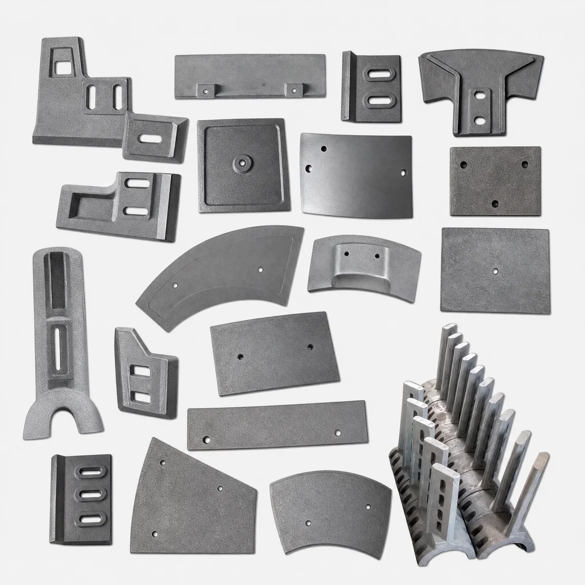
Concrete Mixer Arm Maintenance & Troubleshooting Guide: Preventing Keyway Shearing, Arm Fracture, and Blade Alignment Failures
Loose hub clamp bolts and misaligned mixing arms are the leading causes of mixer shaft keyway shearing and severe liner gouging. Follow this field maintenance guide to calibrate arm pitch and eliminate emergency downtime.
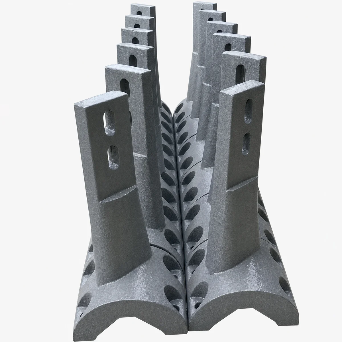
The Engineering Guide to Concrete Mixer Arms: Ductile Iron GS700, Cast Alloy Metallurgy, and Fatigue Resistance
Concrete mixer arms endure massive cyclical bending moments, aggregate impact, and torsional shear. Specifying high-spheroidization ductile iron (GS700) or forged alloy steel prevents catastrophic arm snap and protects mixer drive gearboxes.