Concrete Mixer Arm Maintenance & Troubleshooting Guide: Preventing Keyway Shearing, Arm Fracture, and Blade Alignment Failures
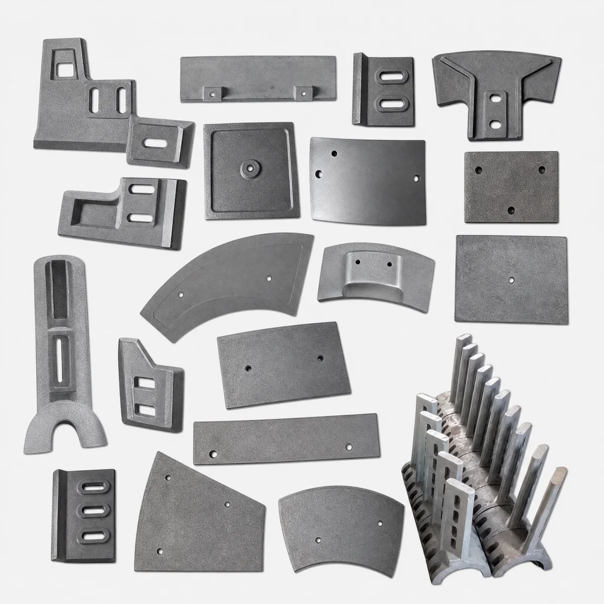
An authoritative field maintenance guide for batching plant engineers. Learn how to diagnose mixer arm bending, prevent shaft keyway shearing, align left/right/central mixing arms, and optimize clamp bolt torque.
In commercial ready-mix concrete batching plants and precast concrete manufacturing facilities, twin-shaft concrete mixers perform high-speed mixing cycles under extreme dynamic loads. Within the mixing trough, mixing arms for concrete mixers act as the primary structural links connecting the heavy rotating drive shafts to the mixing blades.
Because mixing arms operate constantly submerged in abrasive, dense concrete slurry, they are exposed to severe cyclic bending forces, aggregate wedging impacts, and slurry scouring. Over time, neglected clamp bolt tensioning or improper arm alignment can lead to disastrous failure modes—including cracked arm necks, sheared hub keyways, loose clamping splits, and misaligned blade tips that score deep grooves into drum liners.
This practical field maintenance guide, authored by the RAXMEK Field Engineering & Maintenance Services Group, provides plant engineers, maintenance technicians, and equipment operators with diagnostic failure troubleshooting matrices, bolt torque specifications, pitch calibration procedures, and step-by-step replacement protocols to maximize mixer reliability.
1. Diagnostic Troubleshooting Guide: Common Mixing Arm Failure Modes
During weekly preventive maintenance inspections, maintenance crews frequently encounter physical symptoms indicating mixing arm distress. The diagnostic matrix below identifies root causes and provides field-tested corrective actions:
| Observed Failure Symptom | Physical Appearance | Root Cause Analysis | Corrective Maintenance Action |
|---|---|---|---|
| Sheared Hub Keyway / Flat Deformation | Internal keyway wall rounded or gouged out; arm rocks on shaft | Loose clamp bolts allowed micro-fretting; low yield strength hub material | Replace arm with RAXMEK GS700 ductile iron arm; re-torque Grade 10.9 clamp bolts to specification. |
| Fracture at Arm Neck | Complete snap at neck junction between hub and blade mounting pad | High-cycle bending fatigue combined with stone wedging shock load | Replace broken arm; check mixer overload relief valve; verify max aggregate size (under 40mm). |
| Liner Gouging / Deep Grooving | Concentric score marks cut into central drum liners | Misaligned arm pitch or bent arm neck pushing blade tip directly into liner | Straighten or replace bent arm; calibrate blade clearance to 4.0mm using feeler gauges. |
| Clamping Bolt Shearing | Socket cap screws snapped or backed out completely | Excessive vibration, failure to apply threadlocker, or improper initial torque | Use genuine Grade 10.9 / 12.9 fasteners; apply medium-strength threadlocker (Loctite 243). |
| Slurry Washing of Arm Neck | Deep erosion grooves worn into leading edge of the arm neck | Abrasive slurry scouring in high-volume granite/basalt concrete mixing | Install protective high-chromium wear sleeves or upgrade to RAXMEK hardfaced mixing arms. |
2. Spatial Alignment & Pitch Calibration: Left, Right, Central & Scraper Arms
Inside a twin-shaft concrete mixer, mixing arms are arranged in a multi-phase spiral configuration along the two counter-rotating shafts. Maintaining exact spatial alignment and pitch angles during arm replacement is essential to ensure uniform 3D slurry circulation.
Mixing Arm Placement & Pitch Alignment Schema
Propels concrete slurry from left to right toward central mixing zone.
Propels concrete slurry from right to left, creating 3D figure-8 circulation.
Handles maximum crossover turbulence at central shaft overlap zone.
Cleans end wall liners & protects shaft seal housings from grout build-up.
2.1 The Consequences of Incorrect Arm Pitching
If a Left Side Mixing Arm is accidentally installed in a Right Side Arm position during maintenance, the helical slurry flow is disrupted. Concrete is pushed outward against the end walls instead of circulating through the center. This results in:
- Increased Mixing Time: Batch homogenization time increases from 30 seconds to over 60 seconds.
- Motor Overload: Drive motor current consumption spikes by 20% to 35% due to hydraulic dead-locking.
- Severe Shaft Seal Wear: Cement slurry is packed under pressure directly against end-wall shaft seals.
3. Clamping Torque Specifications & Fastener Selection
Mixing arms are clamped onto main mixer shafts using split-hub designs held by high-tensile socket head cap screws. Using incorrect bolt grades or inadequate tightening torque is the primary cause of hub fretting and keyway shearing.
CRITICAL FASTENER WARNING
Never use standard Grade 4.8 or 8.8 commercial bolts on mixing arm hub clamps. High-torque concrete mixers require Grade 10.9 or Grade 12.9 alloy steel fasteners. Torque all bolts using a calibrated torque wrench and apply medium-strength threadlocking compound.
Recommended Clamp Bolt Torque Specifications
| Bolt Diameter (Metric) | Fastener Grade | Thread Pitch | Recommended Torque (N·m) | Recommended Torque (ft-lbs) |
|---|---|---|---|---|
| M16 | Grade 10.9 | 2.00 mm | 240 to 260 N·m | 177 to 192 ft-lbs |
| M18 | Grade 10.9 | 2.50 mm | 330 to 360 N·m | 243 to 265 ft-lbs |
| M20 | Grade 10.9 / 12.9 | 2.50 mm | 480 to 520 N·m | 354 to 383 ft-lbs |
| M24 | Grade 12.9 | 3.00 mm | 820 to 880 N·m | 605 to 649 ft-lbs |
4. Aggregate Size Dynamics & Impact Load Management
The size and density of coarse aggregate dropped into the mixer drum determine the mechanical impact severity experienced by the mixing arms:
Generates low impact kinetic energy. Standard RAXMEK GS700 ductile iron arms provide unlimited fatigue life under continuous batching.
Large rocks falling from 2-meter weigh hopper heights generate high shock impacts. Requires forged 42CrMo4 steel mixing arms or heavy-section GS700 castings.
5. Step-by-Step Mixing Arm Replacement & Shaft Alignment Protocol
When replacing broken or worn mixing arms during plant overhauls, follow RAXMEK’s standard 6-step engineering protocol:
6-Step Mixing Arm Replacement Workflow
Step 1: Safety Lockout & Demolition
Disconnect main circuit breakers for mixer motors. Lock pneumatic discharge doors with mechanical safety pins. Unbolt damaged mixing blades and remove clamping bolts from the broken mixing arm hub.
Step 2: Shaft Flat & Keyway Inspection
Thoroughly clean the main square or hexagonal shaft surface using a wire wheel and solvent. Inspect shaft flats for burrs or fretting grooves. File down any raised metal burrs to ensure the new arm hub seats perfectly flat.
Step 3: Positioning & Threadlocking
Apply medium-strength threadlocking fluid (Loctite 243) to clamp bolt threads. Slide the replacement RAXMEK mixing arm onto the shaft flat, double-checking the Left vs. Right pitch orientation mark cast on the arm neck.
Step 4: Blade Clearance Calibration & Final Torquing
Mount the mixing blade onto the arm’s blade pad. Use feeler gauges to set a uniform 4.0mm clearance between the blade edge and the trough liners. Tighten hub clamp screws in an alternating cross-pattern to full recommended torque.
6. Preventive Maintenance Checklist for Plant Engineers
Implement this structured maintenance routine to prevent unexpected mixing arm failures and extend wear component lifespan:
Daily Shift Checklist
- Acoustic & Vibration Monitoring: Listen for unusual metallic thumping inside the mixing trough that indicates a loose arm or wedged stone.
- Visual Hub Clearance Check: Verify that cement slurry is not weeping out from behind mixing arm hub clamping splits.
Weekly Maintenance Checklist (Every 5,000 m³)
- Clamp Bolt Torque Check: Apply a torque wrench to all mixing arm clamping screws to verify bolts have not loosened under vibration.
- Blade-to-Liner Clearance Inspection: Check blade edge clearance across all arms. Adjust arm mounting slots if clearance exceeds 6.0mm.
Monthly Maintenance Checklist (Every 25,000 m³)
- Arm Neck NDT Inspection: Visual and dye-penetrant check of arm neck radius zones for micro-cracks or severe slurry washing.
- Shaft Keyway Play Check: Manually rock mixing blades back and forth to detect any angular play between the hub bore and shaft flats.
7. Partner with RAXMEK for Reliable Mixer Wear Parts
At RAXMEK, we engineer high-performance wear components that keep global concrete batching operations running without interruption. Our product range includes GS700 ductile iron mixing arms, high-chromium mixer liners, cast mixing blades, side scrapers, concrete cutting discs, and diamond saw blades.
- OEM Interchangeability: 100% exact dimension match for BHS, SICOMA, Liebherr, Teka, SIMI, ELKON, MEKA, and custom twin-shaft concrete mixers.
- Superior Metallurgy: GS700 high-strength pearlitic ductile iron and forged 42CrMo4 alloy options with zero internal porosity guarantees.
- Global Technical Support: Experienced application engineers available to diagnose premature wear issues and provide custom metallurgical solutions.
Request Technical Engineering Assistance
Ready to resolve mixing arm breakage issues and reduce batching plant maintenance costs? Contact RAXMEK technical sales today for expert guidance, CAD engineering drawings, or a fast B2B quotation.
- Email: info@raxmek.com / sales@votne.com
- Technical Consultation: Submit your mixer model and aggregate specifications via our Online Contact Form to consult with a wear parts specialist.
Теги
Похожие ресурсы
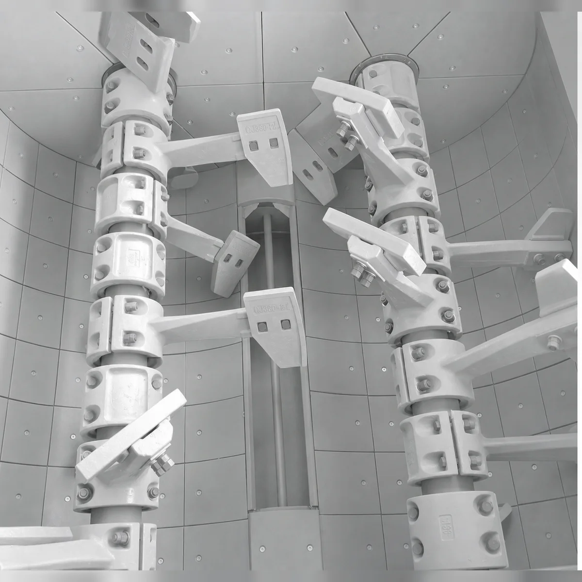
Concrete Mixer Liner Maintenance & Replacement Guide: Troubleshooting Wear Patterns, Bolt Torque Specs, and Downtime Reduction
Uneven liner wear and loose countersunk bolts are the leading causes of mixer drum gouging and unscheduled downtime in batching plants. This guide covers step-by-step maintenance protocols, clearance tuning, and failure prevention.
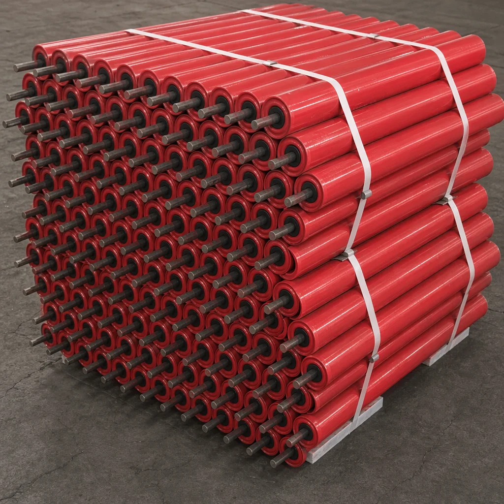
How to Select and Optimize Conveyor Rollers for Heavy-Duty Industrial Applications
Conveyor rollers are the unsung heroes of bulk material handling. Specifying the correct tube thickness, bearing clearance, and sealing system can reduce operational downtime by up to 40%.
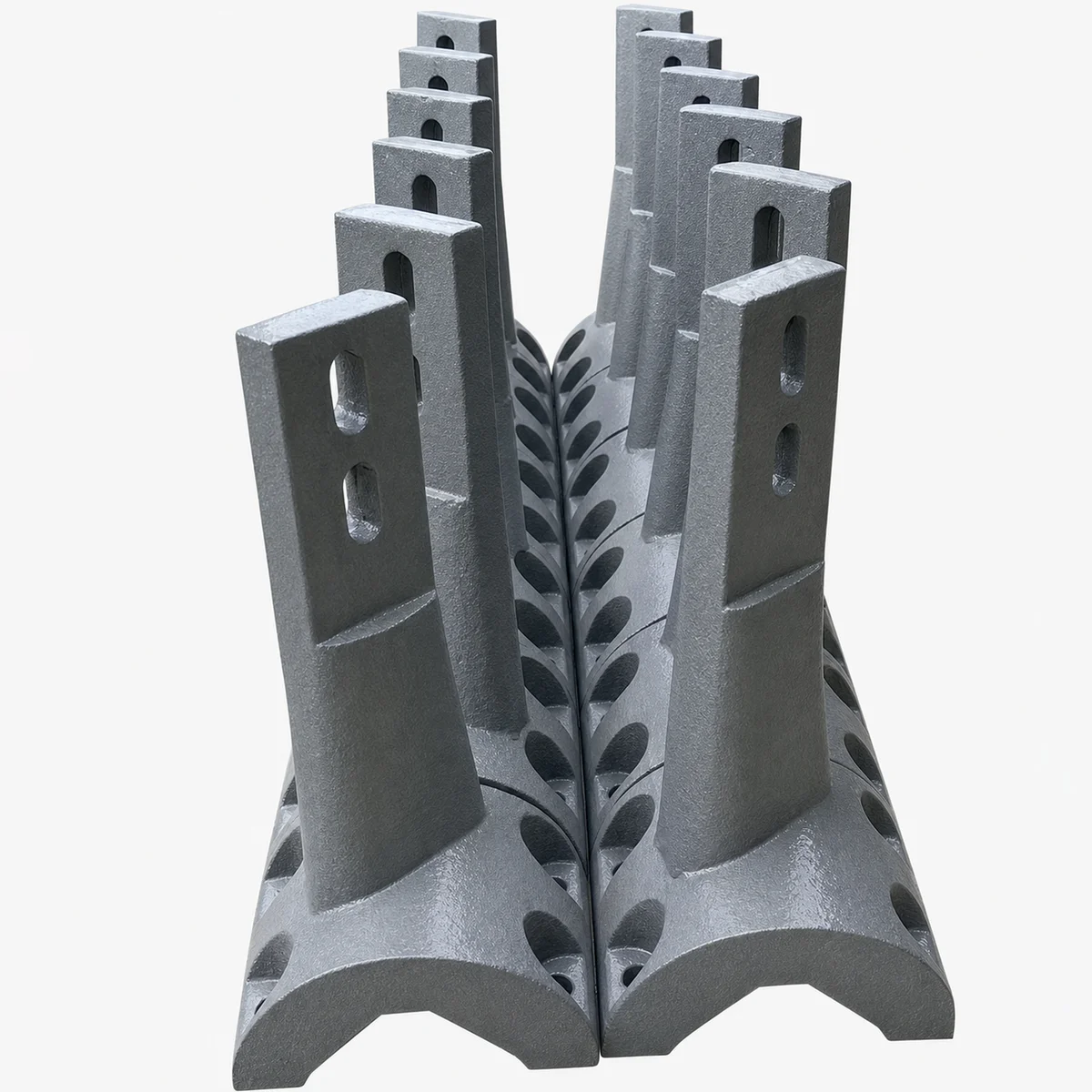
The Engineering Guide to Concrete Mixer Arms: Ductile Iron GS700, Cast Alloy Metallurgy, and Fatigue Resistance
Concrete mixer arms endure massive cyclical bending moments, aggregate impact, and torsional shear. Specifying high-spheroidization ductile iron (GS700) or forged alloy steel prevents catastrophic arm snap and protects mixer drive gearboxes.