How to Select and Optimize Conveyor Rollers for Heavy-Duty Industrial Applications
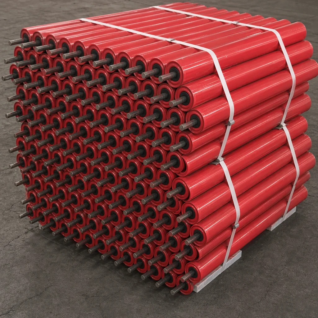
A comprehensive engineering guide on selecting, calculating, and optimizing heavy-duty conveyor rollers. Learn how steel grades, C3 bearings, and triple labyrinth seals maximize bulk handling efficiency.
In bulk material handling operations—ranging from deep-pit mining and cement manufacturing to coal-fired power plants and steel mills—conveyor systems are the primary arteries of production. At the heart of these systems are conveyor rollers (idlers). Although they are often treated as simple consumables, rollers account for up to 60% of a conveyor’s rotating parts and significantly influence the system’s overall energy consumption, belt wear, and operational uptime.
A single seized roller can quickly wear through a premium conveyor belt, leading to catastrophic belt tears and unscheduled downtime that can cost upwards of $50,000 per hour in lost productivity.
This technical guide provides a deep dive into the engineering parameters, material science, and selection criteria required to optimize conveyor roller performance in heavy-duty industrial environments.
1. The Anatomy of a High-Performance Conveyor Roller
To withstand continuous loads, abrasive dust, and moisture, every component of a conveyor roller must be engineered to precise tolerances.
The Tube (Shell)
The tube is the outer shell that contacts the conveyor belt.
- Material Grade: High-quality carbon steel (typically Q235 or equivalent ASTM A53 Grade B) is the industry standard. For highly corrosive environments, stainless steel (SUS304/316) or composite materials are specified.
- Wall Thickness: Heavy-duty applications require a wall thickness of 4.0mm to 6.0mm to resist wear from abrasive materials and withstand the impact at loading points.
- Total Indicated Runout (T.I.R.): High T.I.R. causes structural vibration and accelerates bearing wear. Premium rollers are machined to achieve a T.I.R. of < 0.5mm, ensuring smooth, concentric rotation at high belt speeds (up to 5.0 m/s).
The Shaft
The shaft transmits the radial and axial loads from the roller shell to the conveyor framework.
- Material: Precision cold-drawn round steel (such as C45 carbon steel / 45# steel) is utilized. It is ground and polished to a tolerance of h9/h10 to ensure a precise interference fit with the bearing inner ring.
- Deflection Limits: Under maximum load, shaft deflection at the bearing center must not exceed 0.005 radians (approx. 15 minutes of a degree) to prevent bearing misalignment and premature failure.
Bearings: The Core of Rotation
Bearings must handle high radial loads while accommodating shaft deflection and thermal expansion.
- Type: Deep groove ball bearings (typically 6204, 6205, 6306, or 6308 series) are standard.
- Clearance Class: Standard clearance bearings will seize under shaft deflection. Heavy-duty rollers require C3 or C4 internal clearance. This extra radial play allows the bearing to rotate freely even when the shaft deflects slightly under heavy loads or expands due to frictional heat.
- Origin and Quality: Specifying reputable brands (such as SKF, FAG, NSK, or premium certified B2B equivalents) ensures consistent steel purity and fatigue life ($L_10$ life exceeding 50,000 hours).
The Sealing System: Defense Against Contaminants
Over 80% of conveyor roller failures are caused by bearing contamination. A robust sealing system is critical.
- Triple Labyrinth Seals: A multi-stage labyrinth seal made of Polyoxymethylene (POM) or Nylon-6 creates a tortuous, grease-filled path. Centrifugal force flings dust and water outward, preventing contaminants from reaching the bearing cavity.
- Contact Seals & Rain Caps: A secondary outer lip seal (rubbing seal) combined with a galvanized steel dust/rain cap provides the first line of defense against direct water sprays and large grit.
2. Material Selection: Steel vs. HDPE vs. Polyurethane
Choosing the right roller material depends on the chemical, physical, and mechanical demands of the application.
| Parameter | Heavy-Duty Steel | Composite / HDPE | Polyurethane Lagged |
|---|---|---|---|
| Tensile Strength | High (~400 MPa) | Medium (~25 MPa) | High (Core dependent) |
| Weight | Heavy (Base reference) | 50% - 60% Lighter | Heavy |
| Corrosion Resistance | Poor (Requires painting/galvanizing) | Outstanding | Excellent |
| Material Buildup | Prone to scaling | Non-stick surface | Highly resistant |
| Noise Level | Standard | Reduced (by 5-10 dB) | Standard |
| Primary Use Cases | High-tonnage mining, iron ore, coal, loading zones. | Chemical plants, fertilizer ports, acidic environments, noise-sensitive areas. | Sticky materials, high-moisture return runs, belt-tracking zones. |
When to Specify HDPE (High-Density Polyethylene)
HDPE rollers are increasingly replacing steel in specialized applications. Because they are lightweight, they reduce the startup torque of the conveyor system, leading to lower energy consumption. Furthermore, if an HDPE roller wears through, it will not produce a sharp, jagged edge that can slice the conveyor belt—a common failure mode of worn steel rollers.
3. Engineering Calculations for Roller Selection
To select the correct CEMA (Conveyor Equipment Manufacturers Association) class, design engineers must calculate the load acting on the idler rolls.
Formula: Idler Load Calculation
The design load (Load_idler) on a carrying idler is calculated using the following formula:
Loadidler = ((Wb + Wm) × Si × Kim × Ksp) + Iw
Where:
- W_b = Belt weight per unit length (kg/m)
- W_m = Material weight per unit length (kg/m) = Capacity (t/h) / (3.6 * Belt Speed (m/s))
- S_i = Idler spacing (m) (typically 1.2m to 1.5m for carrying runs)
- K_im = Impact factor (1.0 for normal runs, 1.5 to 2.0 at loading points)
- K_sp = Slope factor (adjusts for conveyor inclination)
- I_w = Weight of the rotating parts of the idler (kg)
CEMA Classification Reference
Once the load is calculated, select the corresponding CEMA class to ensure the shaft and bearing combination can handle the forces:
- CEMA B: Light duty, shaft diameter 17mm, belt widths up to 1000mm.
- CEMA C: Medium duty, shaft diameter 20mm, belt widths up to 1500mm. (Common in cement and aggregate plants).
- CEMA D: Heavy duty, shaft diameter 25mm, belt widths up to 1800mm. (Standard for coal and mining).
- CEMA E: Extra heavy duty, shaft diameter 30mm/40mm, high-capacity mining.
- CEMA F: Extreme duty, shaft diameter 45mm+, high-tonnage overland conveyors.
4. Root Cause Analysis of Common Roller Failures
Understanding how rollers fail allows maintenance teams to implement targeted preventive strategies.
Conveyor Roller Failure Modes
1. Bearing Contamination
- Water Ingress: Leads to internal rust, corrosion, and grease wash-out.
- Dust Ingress: Micro-fine particles mix with grease, creating an abrasive paste that locks rotation.
- Preventive Measure: Upgrade to multi-stage labyrinth seals packed with lithium-complex grease.
2. Shell & Shaft Degradation
- Abrasive Wear: Material carryback grinds down the steel shell wall thickness.
- Belt Misalignment: Off-center loads create high friction and uneven wear patterns.
- Shaft Deflection: Exceeding load limits bends the shaft, causing bearing misalignment.
Failure Mode 1: Bearing Seizure
- Symptom: The roller stops rotating, causing flat spots to wear into the shell.
- Root Cause: Inadequate sealing allows micro-fine silica or coal dust to penetrate the labyrinth seal, absorbing the oil from the bearing grease and creating an abrasive paste.
- Solution: Upgrade to a triple labyrinth seal packed with high-temperature, water-resistant lithium-complex grease filled to 65% volume.
Failure Mode 2: Shell Wear-Through (“Can Opener” Effect)
- Symptom: The steel shell wears thin and splits, creating sharp metal edges.
- Root Cause: Carrying abrasive materials (such as quartz or sinter) that spill onto the return run and grind between the belt and the roller.
- Solution: Install belt scrapers, plow cleaners, or replace steel rollers with rubber-lagged or polyurethane-coated shells in high-wear zones.
Failure Mode 3: Shaft Bending
- Symptom: The roller rotates with a heavy wobble, destroying the bearings within days.
- Root Cause: Exceeding the maximum load capacity during material surges or high-impact drops at loading chutes.
- Solution: Increase shaft diameter, reduce idler spacing at the loading point, or install dedicated impact slider beds.
5. Maximizing ROI: The Total Cost of Ownership (TCO) Model
When procurement departments purchase conveyor rollers based solely on the lowest unit price, they often lose money due to increased maintenance labor and premature replacements.
TCO Case Study: 1km Overland Conveyor (500 Idler Sets)
Consider a mining operation comparing Standard Rollers with Premium Labyrinth-Sealed Rollers:
-
Standard Roller:
- Unit Cost: $35
- Average Lifespan: 1.5 Years
- Replacement Labor Cost per Roller: $50
- Cost over 6 Years (4 cycles): $(35 + 50) \times 4 = $340$ per roller position.
-
Premium VOTNE Roller (Triple Labyrinth Seal, C3 SKF Bearings, Q235 Shell):
- Unit Cost: $65
- Average Lifespan: 6 Years (Zero replacements required during the period)
- Cost over 6 Years (1 cycle): (65 + 0) = $65 per roller position.
Direct Savings: By investing in premium rollers, the operation saves $275 per roller position over 6 years. Across a 1km conveyor with 1,500 individual rollers, this translates to $412,500 in direct savings, excluding the massive savings from avoided conveyor belt wear and unplanned downtime.
Conclusion: Partner with VOTNE for Engineered Reliability
Selecting the right conveyor roller is a balance of mechanical engineering, material science, and financial analysis. At VOTNE, we don’t just supply parts—we engineer solutions.
Our heavy-duty steel and composite rollers are manufactured to strict ISO 9001 standards, featuring double-sided welding, dynamic balance testing, and advanced triple-labyrinth sealing systems designed to withstand the harshest environments on earth.
Ready to optimize your conveyor system’s reliability? Contact our engineering support team today for a comprehensive system audit, customized technical drawings, or a competitive B2B quotation.
- Email: engineering@votne.com
- Technical Support: Fill out our Contact Form to consult with a B2B parts specialist.
Tag
Risorse Correlate
Concrete Mixer Liner Maintenance & Replacement Guide: Troubleshooting Wear Patterns, Bolt Torque Specs, and Downtime Reduction
Uneven liner wear and loose countersunk bolts are the leading causes of mixer drum gouging and unscheduled downtime in batching plants. This guide covers step-by-step maintenance protocols, clearance tuning, and failure prevention.
Concrete Mixer Arm Maintenance & Troubleshooting Guide: Preventing Keyway Shearing, Arm Fracture, and Blade Alignment Failures
Loose hub clamp bolts and misaligned mixing arms are the leading causes of mixer shaft keyway shearing and severe liner gouging. Follow this field maintenance guide to calibrate arm pitch and eliminate emergency downtime.
The Engineering Guide to Concrete Mixer Arms: Ductile Iron GS700, Cast Alloy Metallurgy, and Fatigue Resistance
Concrete mixer arms endure massive cyclical bending moments, aggregate impact, and torsional shear. Specifying high-spheroidization ductile iron (GS700) or forged alloy steel prevents catastrophic arm snap and protects mixer drive gearboxes.